Inspired by another
post, I decided it was time to create my own bench power supply. A good bench power supply is something that can be really handy to a burgeoning electronics enthusiast. It makes it much easier to prototype quickly because you don't have to first figure out the power circuit before getting to what you are actually excited about tinkering with.
This is a fairly simple project. It is mostly just re-routing wires from one place to another. The main component is an ATX power supply, which can be found in almost any desktop tower computer. Besides that I just needed to order an appropriate
switch and some
banana plug binding posts.
Desktop power supplies can range greatly in total power output, but for hobby electronics the most basic 150-250 watt power supplies are way more than enough power for most projects. What makes an ATX power supply ideal for this, is that it outputs 4 different standard voltages (5V, 3.3V, 12V, -12V), and it is already designed for microelectronics, so the output is very steady with a minimum of noise.
 |
| Power supply from my old Dell desktop |
I recently retired an old computer so I had a power supply on hand to get started. First thing I did was take off the cover and have a look. Next I tested that grounding the green wire would start it up. It did, so I got to work installing the the toggle switch to act as a power switch for the unit.
 |
Drilled hole in the back for the switch.
The smaller hole on the bottom is for a little tab on the washer that
keeps the switch oriented in the right direction |
 |
| The switch installed |
At this point I thought I was on my way to finishing this project, but I hit a major snag. I had stripped the ends of a few of the wires to test what their outputs were. I believe the "always on" 5V wire (purple) shorted to ground. I saw a flash and heard a loud pop, and the power supply no longer worked. Bummer.
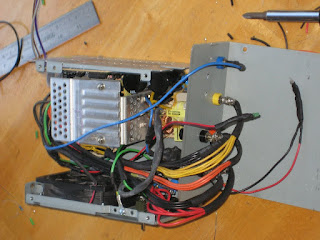
So I needed to find another power supply to finish the project. Luckily my uncle had an old computer hanging around that he was willing to donate to my cause. So I was back in business. This power supply was much more compact, and I wasn't going to have much room to work, but I thought I could make it work.
 |
| Not much room to work... |
So I pulled off the switch an moved it over to the new power supply. Next I figured out where I was going to place the posts and got to drilling the holes. Here is where I hit another snag. I needed to drill the holes out to 3/8" to install the posts properly. What I found was that hand drilling a hole that size in soft steel doesn't work to great. I ended up completely tearing up and warping the power supply case. It wasn't going to work.
 |
| Ruined case. Looks like it was in a gun fight... |
Now I had two busted power supplies. One with dead inards and another with a ruined casing. So now my only option was to take the guts out of the new one and put it in the old case. This worked out ok. two of the pcb mounting holes even lined up. And now I had more room to mount the posts. The only modification I had to make was clipping the main power lines and joining them back together after mounting the guts.
 |
| Guts from viable power supply |
 |
| Case from first power supply |
My second try at drilling the holes was much more successful. A sturdy backing to drill against made a big difference, but it was still touch and go. After that I was able to start mounting the posts. I chose these colors because they match the wiring of the power supply. Red = 5V, Orange = 3.3V, Yellow = 12V, Blue = -12V
 |
| Mounted Binding posts, back |
|
Mounted Binding posts, front |
Wiring the binding posts was just a matter of collecting all the like colored wires and soldering them to the correct post. I split the ground (black) wires in half between two posts. But I did connect the two posts with a couple joining wires so all the ground wires could help share the load.
This power supply also had a wiring for an LED that would be lit when the power cord is connected. I think is serves a second purpose of bleeding the capacitors when the power cord is disconnected, so I made sure to keep it in the design, although I had to extend its wires to get it to the front panel. I also added a blue LED as a power indicator when the unit was turned on and ready for use. I just wired the LED with a resistor directly to the red and black posts from the inside.
 |
| Wiring complete |
 |
| Wiring complete, back |
One of the hardest parts was cramming all the wires in the unit as I was trying to close the case. It took a couple tries to get everything to fit in properly but I got it all in there.
 |
| Finished (except the leds popped out, had to bust out the super-glue to remedy that situation) |
 |
| Power supply off |
 |
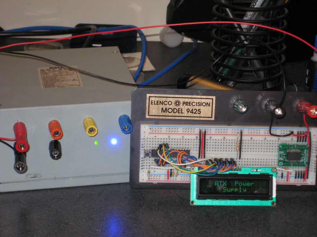
| Power supply in action |
In conclusion, I'm very happy with the project. I was able to re-purpose some old equipment into a very useful tool that I can hopefully get many years use out of.